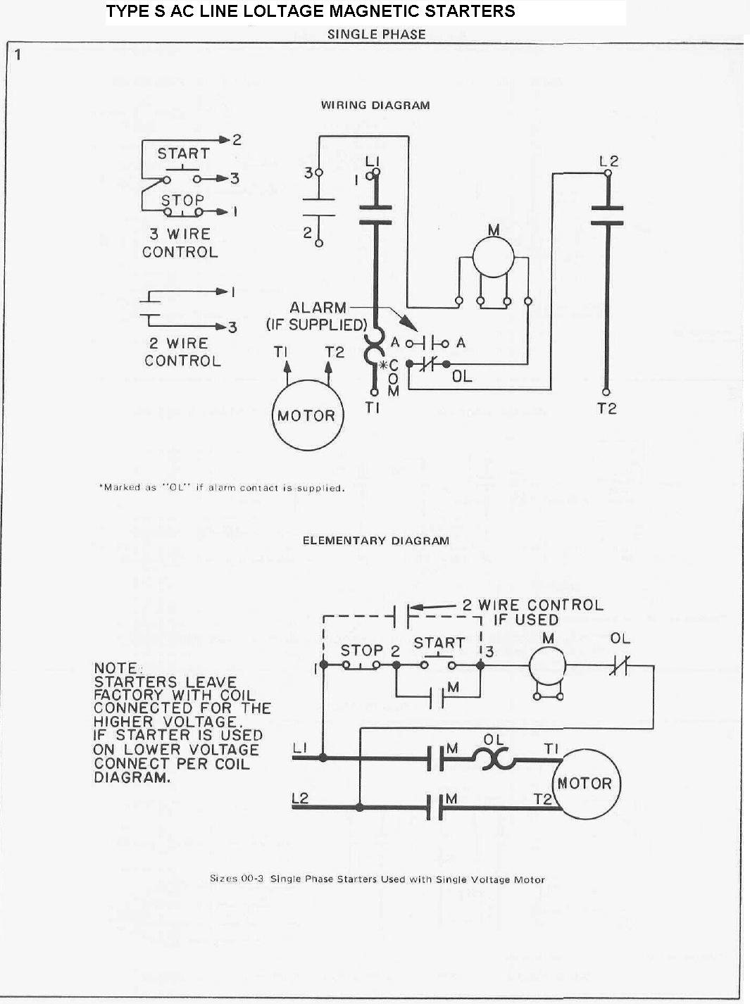
The symbols represent electrical and electronic components. Wiring diagrams use special symbols to represent the switches, light, outlet and electrical equipments. An electronic symbol is a pictogram used to represent various electrical and electronic devices or functions, such as wires, batteries, resistors, and transistors, in a schematic diagram of an electrical or electronic circuit. These symbols are largely standardized internationally today, but may vary from country to country, or engineering. SmartDraw comes with pre-made wiring diagram templates.

Customize hundreds of electrical symbols and quickly drop them into your wiring diagram. Special control handles around each symbol allow you to quickly resize or rotate them as necessary. To draw a wire, simply click on the Draw Lines option on the left hand side of the drawing area. Schematic Symbols As you go through various Parallax microcontroller tutorials, you will see schematics describing the circuits to be built.
Below is a list of common symbols you might see in these schematics. Basics - Wiring Diagram. Embedded Conduit Layout. There are some standard symbols to represent the components in a circuits.

This article gives some of the frequently used symbols for drawing the circuits. There are many electrical and electronic schematic symbols are used to signify basic electronic or electrical device. These are mostly we used for draw circuit diagrams.
Schematics are our map to designing, building, and troubleshooting circuits. Understanding how to read and follow schematics is an important skill for any electronics engineer. This tutorial should turn you into a fully literate schematic reader! How do I create a wiring diagram? How to read electrical schematic diagram?

What is the electrical symbol for a switch? Automotive electrical diagrams provide symbols that represent circuit component functions. For example, a few basic symbols common to electrical schematics are shown as: (1) Switch, (2) Battery, (3) Resistor and (4) Ground. On the right, you will observe some of the most frequently encountered car schematic electrical symbols utilized in professional wiring diagrams. The ideal way to understand wiring diagrams is to take a look at some examples of wiring diagrams.
There various different systems used for schematic symbols around the globe. Although there are some differences between them, the different standards bodies realise the need for common symbols and most are the same. In electronic circuits, there are many electronic symbols that are used to represent or identify a basic electronic or electrical device. Electronic Circuit Symbols.
The actual layout of the components is usually quite different from the circuit diagram. Here is an overview of the most used symbols in circuit diagrams. Circuit symbols are used in circuit diagrams which show how a circuit is connected together.
A large and a small line is suppose to represent one battery cell so that the image below would suggest a two-cell battery of V. The relay are switching devices activated by signals. Most of the time, a small voltage or current is used to switch other voltages or higher currents that may be electromechanical or fully electronic type.
No comments:
Post a Comment
Note: Only a member of this blog may post a comment.