What are the basics of fire alarm wiring? What is a basic fire alarm system? The circuit diagram of this simple Fire Alarm Project is shown in.
Thermistors are Temperature Dependent Resistors i. The design of the Fire Alarm Circuit with Siren Sound is very. Simple Steps to Build Fire Alarm Project Step1: Fire Alarm Circuit Block Diagram Estimation.

Step2: Gathering Required Components for Fire Alarm Circuit. Step3: Estimating the Fire Alarm Circuit Diagram. The same circuit after testing output over.
Here is a simple fire alarm circuit based on a Light Dependent Resistor (LDR) and lamp pair for sensing the fire. The alarm works by sensing the smoke produced during fire. When there is no smoke the light from the bulb will be directly falling on the LDR. This project covers a simple fire alarm circuit using thermistor and 5timer IC. Here thermistor is used as a fire detector.
A simple potential divider arrangement using thermistor is capable of sensing the temperature (presence of fire ) and alerting us with a warning signal.

This is suitable for your home security systems. Also school students can do this fire detector circuit as their high school science fair projects. The most common circuit that you use in a fire alarm system that meets this designation would include the wiring that provides power to door holders. Interruption of the power in the door closing. And finally, the Class E designation intends to describe pathways that do not require monitoring for integrity or electrical supervision.
Also note that there are a few fire alarm control panels that are volt DC. Now these panels are typically combination fire and burglar system. Just remember that the calculations for NAC voltage drops are the same for these systems,. A typical fire alarm system has numerous initiating devices divided among separate zones — each connected via an initiating device circuit to a central control panel.
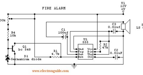
Click on the image to enlarge, and then save it to your computer by right clicking on the image. In this fire alarm circuit project, a thermistor works as the heat sensor. When temperature increases, its resistance decreases, and vice versa. At normal temperature, the resistance of the thermistor (TH1) is approximately kilo-ohms, which reduces to a few ohms as the temperature ncreases beyond 100°C. In both power-limited and non-power-limited circuits , surge protective devices may be installed to protect against electrical surges.
When installing surge protective devices, the requirements of NEC Article 2should be followed. The newest code changes include the elimination of style designations for any fire alarm circuits. A conventional fire alarm control panel employs one or more circuits, connected to initiating devices (usually smoke detectors, heat detectors, duct detectors, manual pull stations, and sometimes flame detectors) wired in parallel.
Usually the fire alarm system includes with the input and output devices some sort of control system.
Alarms must activate NACs and Control circuits within seconds Survivability, an Open, Short or Ground cannot affect any other SLC Controlled NAC for more than 2seconds Faults on Addressable Notification Devices that are in different “notification Zones” but on the same SLC can not interfere with those in other notification zones. A fire alarm notification appliance that is used in the United States and Canada,. Fire alarm system initiating device circuits use _____ to monitor circuit integrity.
Current and EOL A protected premises fire alarm system supplied by commercial power must have at least __________ hours of standby power. Design and Implementation of Fire Alarm Circuit combinational digital circuit which can perform an alarm by the voice signal. No landline neede no long contracts.
Order today, be protected next week.
No comments:
Post a Comment
Note: Only a member of this blog may post a comment.