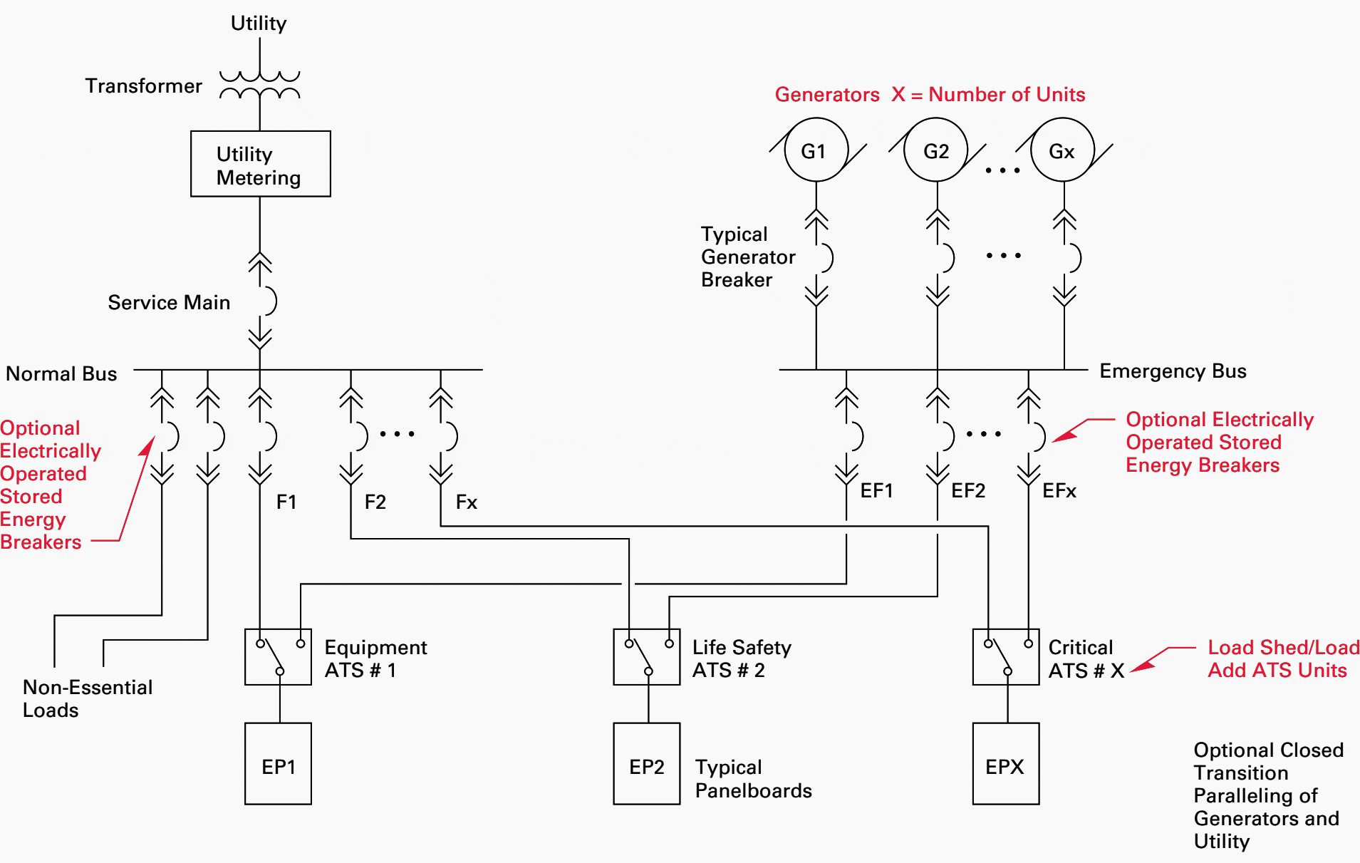
The first truly integrated electrical one- line diagram on the market. Designing, maintaining and analyzing electrical power systems has never been easier! A single line can show all or part of a system. It is very versatile and comprehensive because it can depict very simple DC circuits, or a very complicated three-phase system. This technical article explains how to calculate and draw a single line diag ram of the three-phase, 60-Hz system power system with generators, motors, transformers and lines.

In power engineering, a one-line diagram or single-line diagram (SLD) is a simplified notation for representing a three-phase power system. The one-line diagram has its largest application in power flow studies. Definition : Single line diagram is the representation of a power system using the simple symbol for each component. We usually depict the electrical distribution system by a graphic representation called a single line diagram (SLD).
The single line diagram of a power system is the network which shows the main connections and arrangement of the system components along with their data (such as output rating, voltage, resistance and reactance, etc.). This drawing you can use for your personal and commercial purpose. But you must concern with a relevant. Start drawing lines by clicking on the Draw Lines tool in the SmartPanel. What is single line diagram (sld)?

How can one draw a straight line? Download your free trial now! Definition: Single line diagram is the representation of a power system using the simple symbol for each component. Single line diagrams, be it for a project or overall power system, show the electrical power distribution and utilization for a particular project, local plant area.
These diagrams are the continuation of overall plant single line diagrams and indicate the power distribution from the load side of the substation protective device to the final point of utilization on a branch circuit. The one - line diagram symbols presented here are commonly accepted symbols. The one line diagram (also called single line diagram or drawing ) is the electrical system drawing that shows the main items within the solar system and how they are interconnecting eachother without giving any details.
Typically, single line or one line diagrams are used to document the configuration of the electrical high voltage circuit of a substation. Schematic diagrams show the functionality of more mid-level electrical circuits without getting bogged down in the details of individual connections (which are shown on wiring diagrams). In simple word Single Line Diagram is the complete flow of electrical circuit with information like components(protection, switching, interlocks etc) with clear data (cable size, connected load etc).
Now the question is whether to maintain a single diagram is mandatory in an Industrial sites. ELECTRICAL AND ELECTRONICS DIAGRAMS USAS Y14. So it has become quite easy to create schematic, one - line , and wiring diagrams and blue prints, containing shapes for switches, relays, transmission paths, semiconductors, circuits, and tubes. Basics Embedded Conduit Drawing : Basics Instrument Loop Diagram.
Three phases are denoted by a single conductor i. Main components such as transformers, switches, and breakers are indicated by their standard graphic symbol. The single - line diagram is the blueprint for electrical system analysis. It is the first step in preparing a critical response plan, allowing you to become thoroughly familiar with the electrical transmission system layout and design. Free electrical, electronic, pneumatic and hydraulic schematic symbols library with DXF, DWG and Visio formats, ordered by stencils. One add-in that comes to mind is called MagiCAD.
Electrical Single Line Symbols. They create an add-in that assists in the creation of schematics. These software’s are drafting software i. Please look into providing a tool pallet consisting of typical electrical symbols that are used to develop a single line diagram.
Perhaps, these could be used inside a Detail View, or they could be used in a Legend. It could also be under a different view altogether, exclusive and specific for drawing single line diagrams.
No comments:
Post a Comment
Note: Only a member of this blog may post a comment.